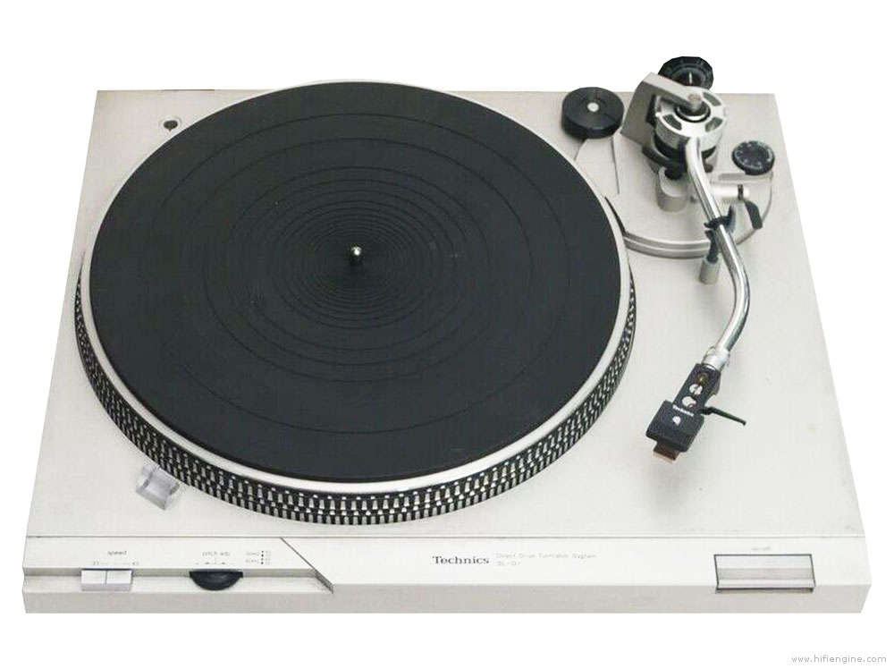
My brother gave me a used turntable (Technics SL-D1) along with a cheap DJ preamp. I didn’t have any vinyl records to play, so he loaned me a few as well. I was once a bit of an audiophile back in the day (early 80’s) but since ditched vinyl as a medium of choice because of how cumbersome it was to play. (not to mention the limited dynamic range, etc.)
Having not listened to vinyl for a few decades, I was curious to playback some familiar tunes – and I was surprised as to how clean the sound coming out of the vinyl was – much better than I remembered.
Slowly I started to listen to more vinyl and started feeling the limitation of the phono amp that I was using. So I looked around the Internet for phono preamp circuits, and formulated the idea of designing a discrete transistor phono preamp.
Late 70’s HiFi Phono Preamp
I found a schematic for Sony TA-F6B. The phono preamp section used a differential FET input stage, current mirror, and class-A gain stage with constant current, among other things that were popular at the time. Pretty much the maxiest form of phono amplifier of the time.
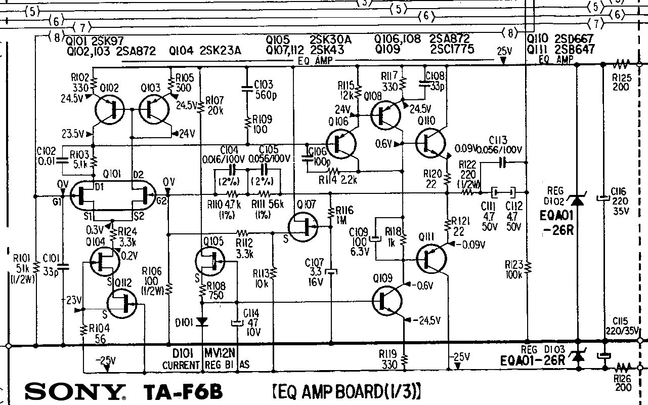
I took the basic concept of using a differential input stage and class-A gain stage with constant current source, and put together a prototype.
I also added a headphone amp built into the same board so that I can easily use headphones.
 (Only one channel shown)
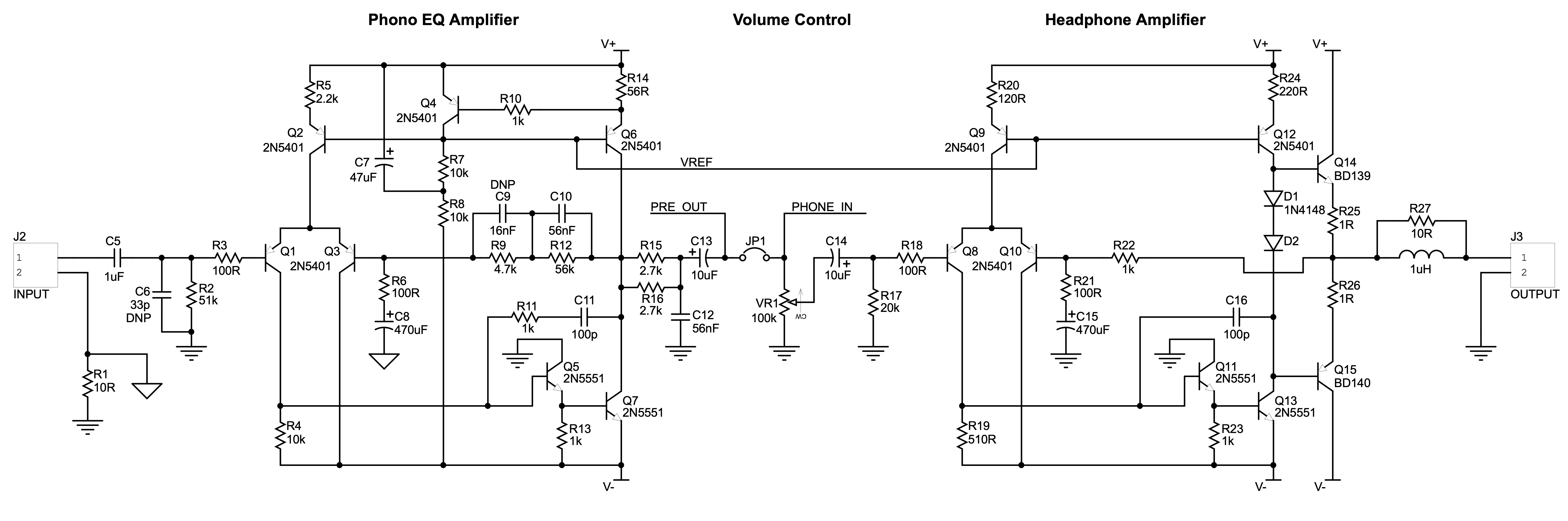
I simply combined parts from different circuits I found everywhere, without much verification.
This prototype managed to produce decent sound (after some tweaking). So I refined the circuit for the 2nd version.
 (Only one channel shown)
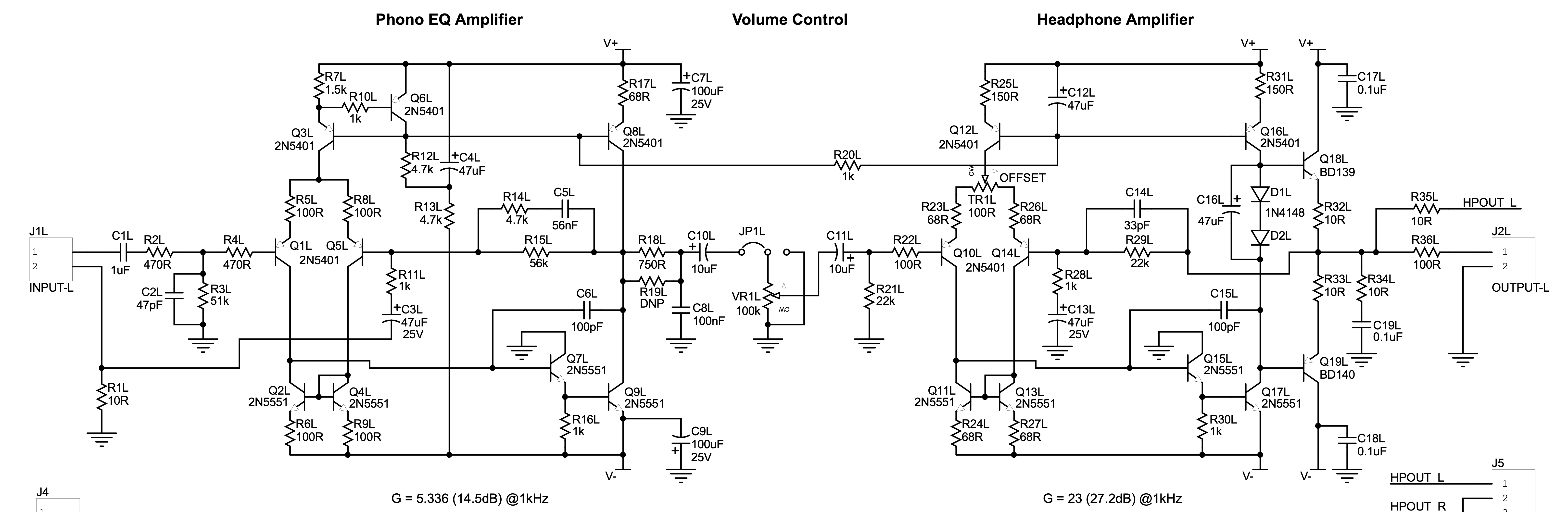
I added a current mirror to further enhance the performance. This version produced good sound, but I goofed on the power supply circuit that was incorporated into the same board. The AC current ran too close to the output transistors and produced a faint hum. Although this was only noticeable using a very sensitive pair of headphones, I decided that this board was a failure.
While I was fixing the PCB design, it occurred to me that I should simplify the circuit. Using many transistors to more or less emulate the op-amp seemed pointless.
There was a simple amplifier topology that I liked called “current feedback amplifier” (I have made a small power amp using this topology and liked the sound before), so I decided to use it for a phono amp.
 (Only one channel shown)
This much simpler circuit produced unexpectedly good sound.
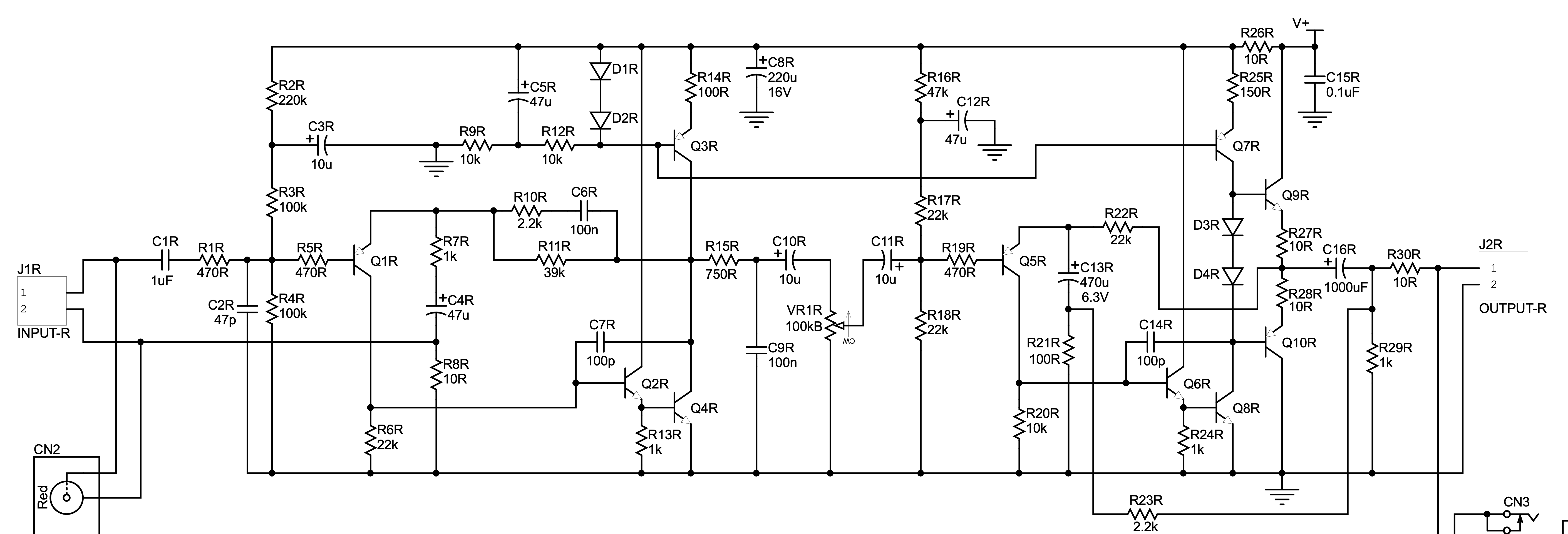
Q2R was included just so that I can experiment with the “beta-enhancer” for the class-A gain stage. I made a second board without it to compare. It turned out that it wasn’t really needed.
After much tweaking of component values and adjusting the gains of each stage, this amplifier started sounding great. Using high-gain, low-noise transistors for the Q1 and Q4 (BC560C and BC550C) made a huge difference especially in very high frequency representation.
One drawback of this (and all single power supply amplifiers) is that they are very sensitive to the power supply noise, so I added an active filter circuit to eliminate ripple from the AC adapter that I was going to use. This filter can reduce the ripple voltage to at least -60dB. Upon hearing I simply can not detect any hum on the output.
Here’s the final circuit.
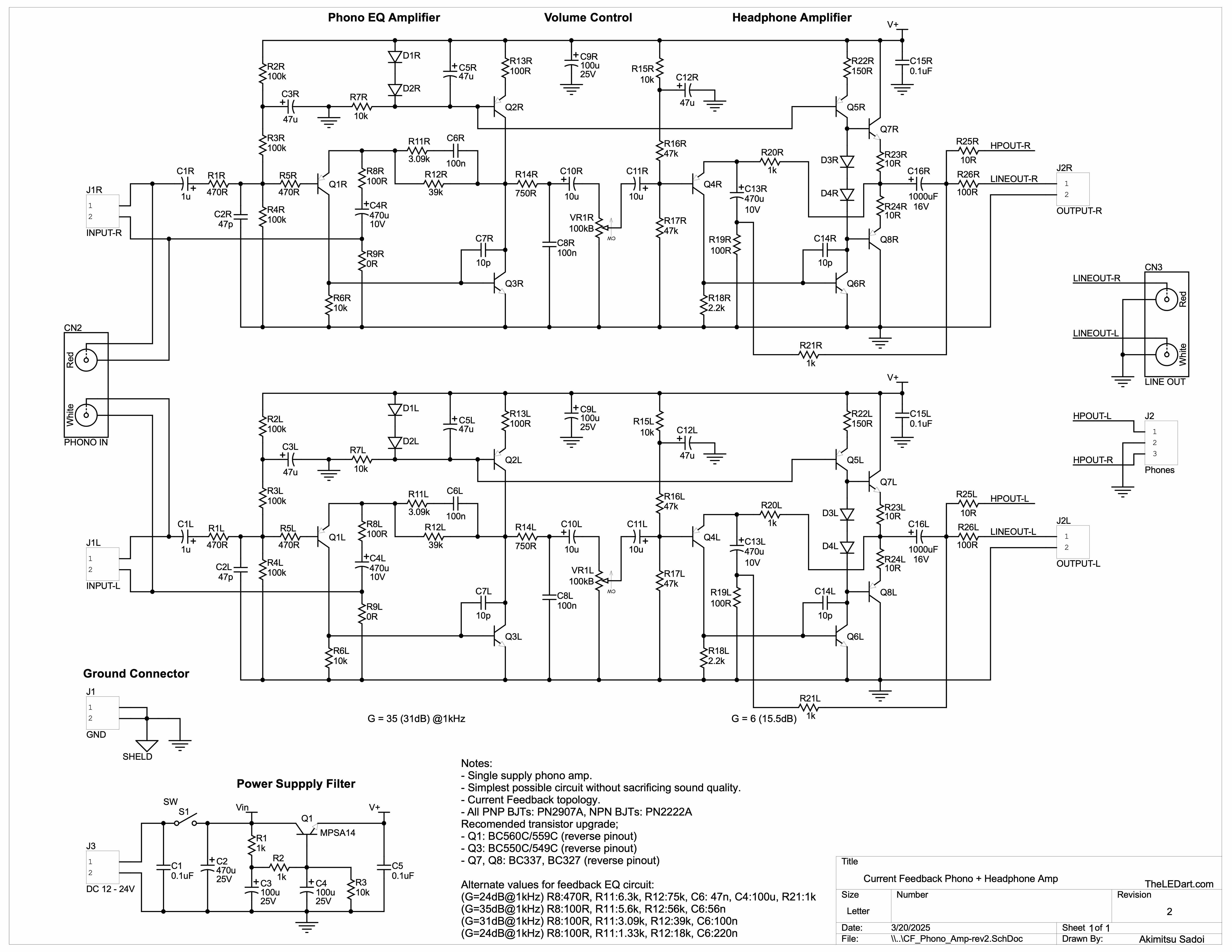
This deceivingly simple circuit produces amazing sound. And it’s more than reasonably low noise.
 Follow